Fan Coil Units Manufacturer: Enviro-Tec
Model#: VHC Series B
Challenges: The rooms were not cooling properly. The property reported the units could not achieve 72 degree room temperature.
- Coil temperature averaged 54.8℉.
- Supply temperature averaged 59℉.
- On the 600 CFM design units, 77% of the unit’s airflow was below the manufacturer’s design specification.
- On the 400 CFM design units, 95% of the unit’s airflow was above the manufacturer’s design specification.
Findings: The site assessment found the units had incorrect flow control valves, which restricted cooling to less than 9000 BTUs rather than the design to cool up to 12,000 BTUs.
Solution:
- Rejuvenate the coils from the back to the front and deep inside the coil’s core.
- Replace the control flow valves with the proper size to increase water flow and bring the units to perform at 12,000 BTU’s.
- Replace the PSC motors and program airflow to the manufacturer’s design specifications.
Results
- Coil temperature dropped by 5℉ from an average of 54.8℉ to 49.8℉.
- Supply temperature dropped by 5.4℉ from an average of 59℉ to 53.6.℉.
- The units were in the airflow target for the respective manufacturer’s design specification.
- Sound decibels dropped by 8.7 dB from an average of 60 dB to 51.3 dB.
- The units cooled the guest rooms from 80 degrees to 72 degrees in 12 minutes.
- The units perform as designed.
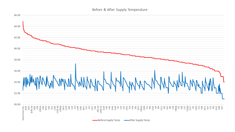
Before & After Supply Temperature
The graph below is sorted by supply temperature from high to low before the coil rejuvenation, flow control valve replacement and EC motor retrofit. The horizontal axis represents the unit’s room number.
The red line demonstrates that before the service the supply temperature ranged from 64.9℉ to 54℉. The average supply temperature was 59℉.
The blue line demonstrates that after the coil rejuvenation, flow control valve replacement and EC motor retrofit the unit’s supply temperature dropped by 5.4℉ from an average 59℉ to 53.6℉.
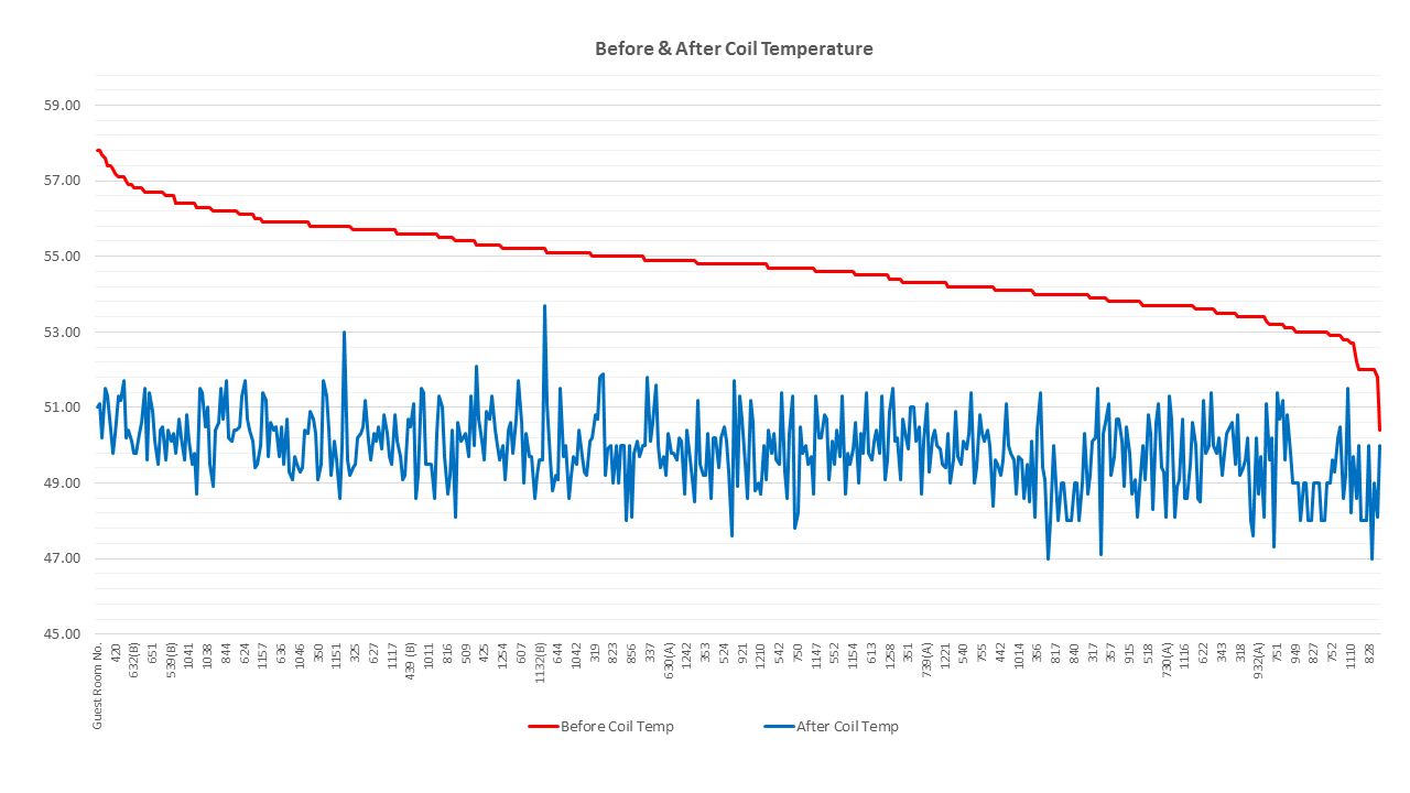
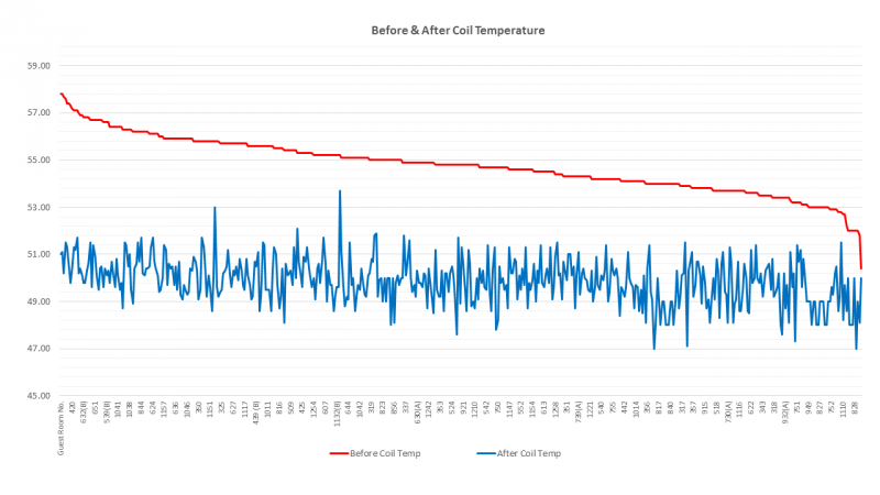
Before & After Coil Temperature
The graph below is sorted by coil temperature from high to low before the flow control valve replacement and EC motor retrofit. The horizontal axis represents the unit’s room number.
The red line’s slope to the right demonstrates that before the service the coil temperature ranged from 58℉ to 51℉. The average coil temperature was 54.8℉.
The blue line demonstrates that after the service 100% of the unit’s coil temperature dropped below 54℉. The average coil temperature after service was 49.8℉.
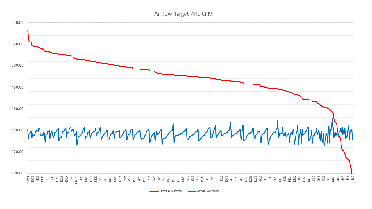
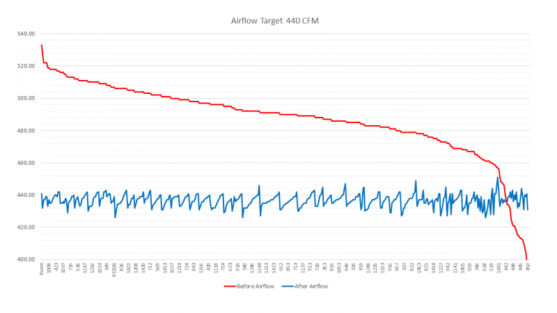
Before & After Airflow Data 440 CFM Design Units
The graph below is sorted by airflow from high to low before coil rejuvenation, flow control valve replacement and the EC motor retrofit. The horizontal axis represents the unit’s room number.
The red line’s slope down to the right demonstrates that the 440 CFM design unit’s airflow before service ranged from 533 to 398 CFM. The airflow averaged 487 CFM.
The blue line demonstrates that after the flow control valve replacement and EC motor retrofit the airflow is programmed to the manufacturer’s design specifications. Each 440 CFM design unit’s high fan airflow was programmed to the airflow design specifications, with an average airflow of 436 CFM.
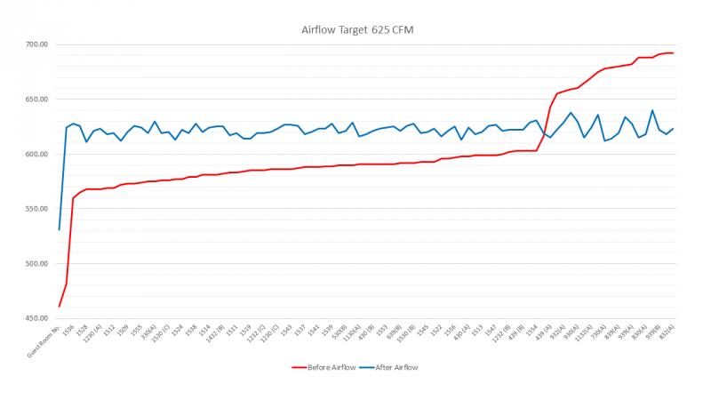
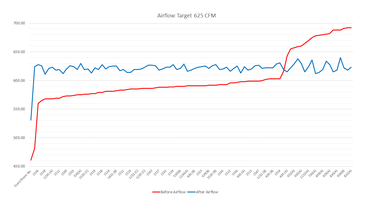
Before & After Airflow Data 625 CFM Design Units
The graph below is sorted by airflow from low to high before coil rejuvenation, flow control valve replacement and the EC motor retrofit. The horizontal axis represents the unit’s room number.
The red line’s slope up to the right demonstrates that the 625 CFM design unit’s airflow ranged from 461 to 692 CFM. The airflow averaged 602 CFM.
The blue line demonstrates that after the flow control valve replacement and EC motor retrofit the airflow is programmed to the manufacturer’s design specifications. Each 625 CFM design unit’s high fan airflow was programmed to the airflow design specifications, with an average airflow of 621 CFM.