CUSTOMER: Full Service Marriott
LOCATION: Houston, TX
INDUSTRY: Hospitality
AIRREVIVE SERVICE: Fan coil unit refurbishment; valve and coil replacement as needed; EC motor retrofit
FAN COIL UNITS: 1983 Lanco W304, W404, Vertical, 4-Pipes
CUSTOMER: Full Service Marriott
LOCATION: Houston, TX
INDUSTRY: Hospitality
AIRREVIVE SERVICE: Fan coil unit refurbishment; valve and coil replacement as needed; EC motor retrofit
FAN COIL UNITS: 1983 Lanco W304, W404, Vertical, 4-Pipes
BACKGROUND
Located in the heart of the internationally recognized Texas Medical Center, this property is the ultimate destination for guests seeking a community of healing, learning and discovery.
The property engaged AirRevive to refurbish, re-commission and repair defective installation and inconsistent airflow from room to room on 452 guest room vertical fan coil units that were manufactured in 1983.
I. Project Challenges
SITE SURVEY FINDINGS
COIL TEMPERATURE CHALLENGES:
SUPPLY TEMPERATURE CHALLENGES:
AIRFLOW CHALLENGES:
II. Project Goals:
The overarching project goal is to extend the life of the fan coil unit asset. The refurbishment process goals to improve the operation of the unit include:
SCOPE OF WORK
AirRevive’s fan coil unit refurbishment and EC motor retrofit process included the following:
III. Supply Temperature
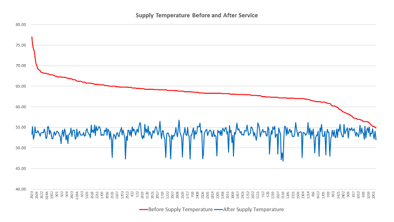
Supply Temperature Before and After Service
Summary: Supply temperature dropped by an average 9.9℉ from 63.4℉ to 53.5℉.
The graph below shows supply temperature sorted from high to low before coil rejuvenation.
The red line demonstrates that before coil rejuvenation the supply temperature ranged from 77℉ to 55℉. The average supply temperature was 63.4℉. The supply temperature was above 55℉ on 100% of the units.
The blue line demonstrates that after coil rejuvenation the supply temperature fell below 56℉ on 99% of the units. The average supply temperature after refurbishment and coil rejuvenation was 53.5℉.
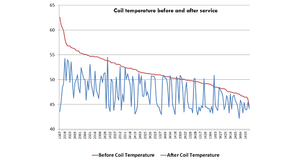
Coil Temperature Before and After Service
Summary: Coil temperature dropped by an average 10.68℉ from 58.71℉ to 48.03℉.
The graph below shows coil temperature sorted from high to low before coil rejuvenation.
The red line demonstrates that before coil rejuvenation the coil temperature ranged from 73.6℉ to 50.1℉. The average coil temperature was 58.6℉. The coil temperature was above 53℉ on 97% of the units and above 56℉ on 90% of the units.
The blue line demonstrates that the refurbishment and coil rejuvenation reduced the coil temperature to below 53℉ on over 95% of the units. The average coil temperature dropped to 48℉.
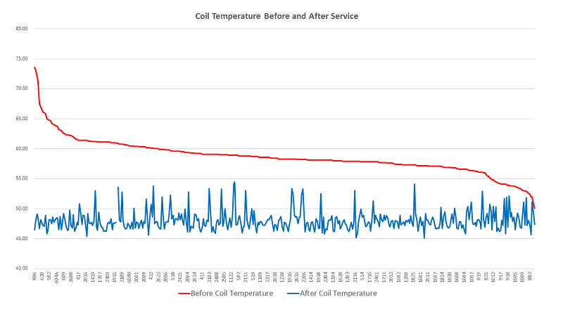
The AirRevive refurbishment resulted in the coil and fins operating at “as-new” performance.
Lowered coil temperature combined with unrestricted airflow prepares the coils for the EC motor retrofit.
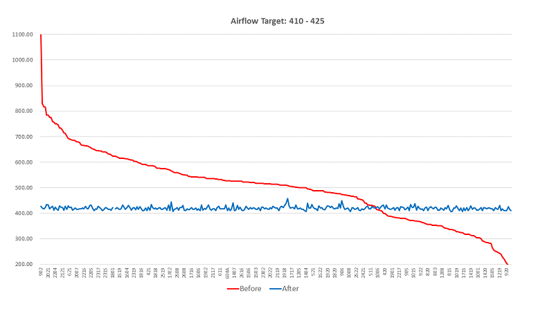
Airflow Before and After Motor Retrofit – Type FC1 & Type FC5
The graph below shows high fan airflow sorted from high to low before the motor retrofit and airflow programming.
Summary: Unit types FC1 and FC5 manufacturer’s high fan airflow design specification is 410-425 CFM. Before the EC motor retrofit the unit’s average airflow was 498 CFM. After the motor retrofit the unit’s average airflow was 420 CFM.
The red line is airflow before motor retrofit. The red line’s slope down to the right demonstrates that the units’ airflow before service ranged from 1099 CFM to 173 CFM.
The blue line demonstrates that after motor retrofit each unit’s high fan airflow is within the original manufacturer’s airflow design specifications of 410-425 CFM.
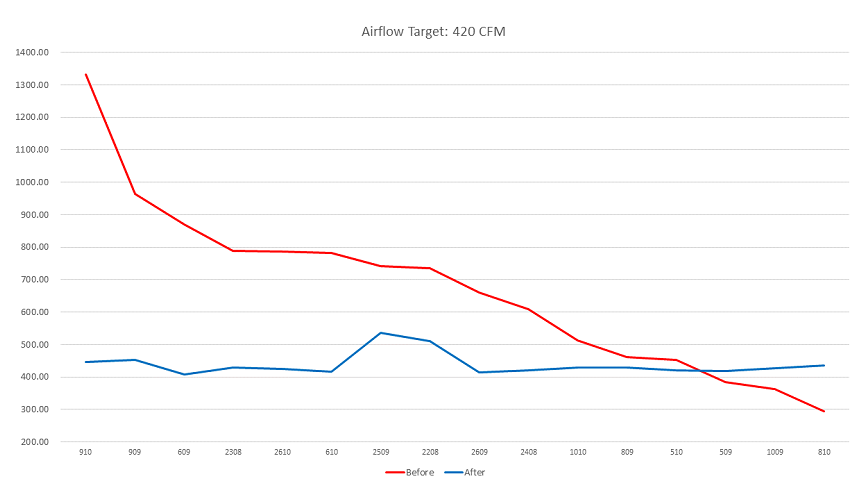
Airflow Before and After Motor Retrofit – Type FC3
The graph below shows high fan airflow sorted from high to low before the motor retrofit and airflow programming.
Summary: Unit type FC3 manufacturer’s high fan airflow design specification is 420-440 CFM. Before the EC motor retrofit the unit’s average airflow was 671 CFM. After the motor retrofit the unit’s average airflow was 438 CFM.
The red line is airflow before the motor retrofit. The red line’s slope down to the right demonstrates that the units’ CFM before service ranged from 1331 CFM to 294 CFM.
The blue line demonstrates that after service the majority of the unit’s high fan airflow is within the original manufacturer’s design specifications of 420 – 440 CFM.
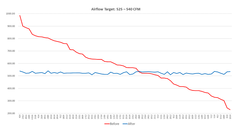
Airflow Before and After Refurbishment – Type FC4
The graph below shows high fan airflow sorted from high to low before the motor retrofit and airflow programming.
Summary: Unit type FC4 airflow design specification is 525-540 CFM. Before the EC motor retrofit the unit’s average airflow was 578 CFM. After the motor retrofit the unit’s average airflow was 524 CFM. The majority of the units fell in the range of 530 CFM.
The red line is airflow before the motor retrofit. The red line’s slope down to the right demonstrates that the units’ CFM before service ranged from 986 CFM to 229 CFM.
The blue line demonstrates that after service each unit’s high fan airflow is within the original manufacturer’s design specifications between 525 and 540 CFM.
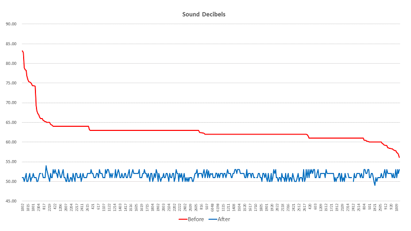
Summary: Sound decibels dropped by an average 11.25db from 62.76db to 51.51db, a decrease of 17.74%.
The graph below is sorted by sound decibels from high to low before refurbishment, installing insulation and the quiet EC motor.
The red line demonstrates that before refurbishment and motor retrofit the sound decibels ranged from 83.20db to 56.1db. The average for the sound decibel readings was 62.78db. 100% of the sound decibel readings were above 57db.
The blue line demonstrates that after refurbishment and the motor retrofit the sound decibel readings for the majority of the units fell below 53db. The average sound decibel reading was 51.51db.
Fan Motor kW Consumption Before & After Refurbishment
Below is the average before and after fan motor kWh energy consumption by unit type, based on a random sampling of 10% of each type of unit.
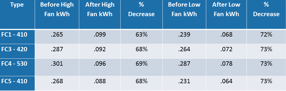
Fan Motor Energy Savings
The projected annual energy savings per fan motor is $97.55, which for the facility is about $44,000 annually.

The EC motor retrofit on an AirRevive refurbished unit is the proven best practice for re-commissioning fan coil units. If the coils are not working uniformly before installing EC motors then the EC motor program will not be optimized.
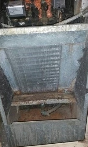
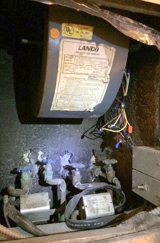
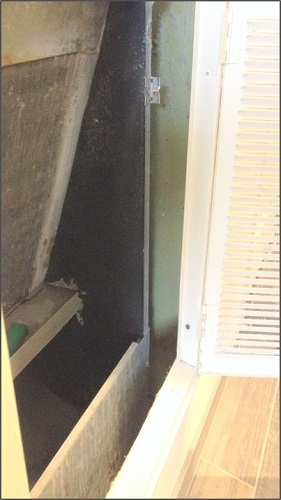
VIII. Before and After Photographs

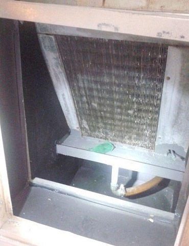
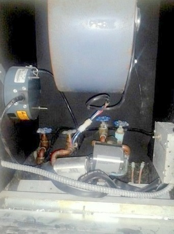
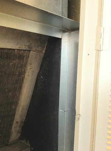
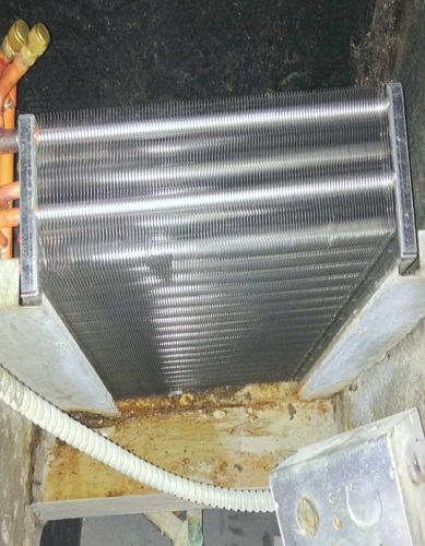
X. FACILITY BENEFITS
The project resulted in the fan coil units operating like new and performing better than new in terms of energy consumption and noise. The benefits to the facility are the following: