CUSTOMER: Full Service Sheraton
LOCATION: Fort Lauderdale, FL
INDUSTRY: Hospitality
AIRREVIVE SERVICE: Fan coil unit refurbishment and control valve replacement
FAN COIL UNITS: 1989 IEC Vertical Fan Coil Units
CUSTOMER: Full Service Sheraton
LOCATION: Fort Lauderdale, FL
INDUSTRY: Hospitality
AIRREVIVE SERVICE: Fan coil unit refurbishment and control valve replacement
FAN COIL UNITS: 1989 IEC Vertical Fan Coil Units
This full service South Florida landmark selected AirRevive to restore its two-hundred and sixty-four 1989 IEC guest room vertical fan coil units during its multi-million dollar renovation.
PROJECT GOALS
1. All HVAC units should be repaired/reconditioned to like-new condition. This will include:
2. If any of these conditions cannot be met, individual components or the entire unit may have to be replaced to obtain an acceptable level of performance.
FAN COIL UNIT REFURBISHMENT AND CONTROL VALVE REPLACEMENT:
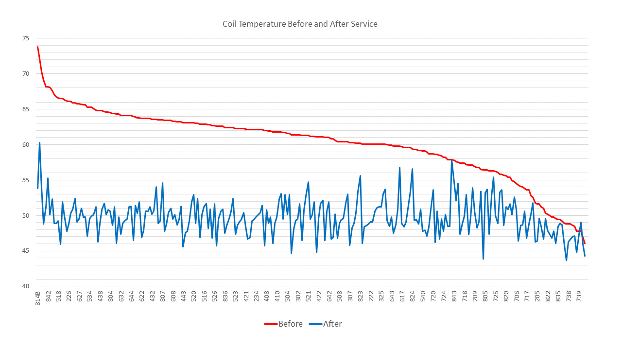
Coil Temperature Before and After Service
Summary: Coil temperature dropped by an average 10.5℉ from 60.2℉ to 49.7℉.
The graph below shows coil temperature sorted from high to low before coil rejuvenation.
The red line shows that before the coils were rejuvenated the coil temperature ranged from 73.8℉ to 46.1℉. The average coil temperature was 60.2℉. The coil temperature was above 54℉ on 88% of the units.
The blue line shows that after the coils were rejuvenated the coil discharge temperature for 98% of the units is below 55℉. The average coil temperature after service is 49.7℉.
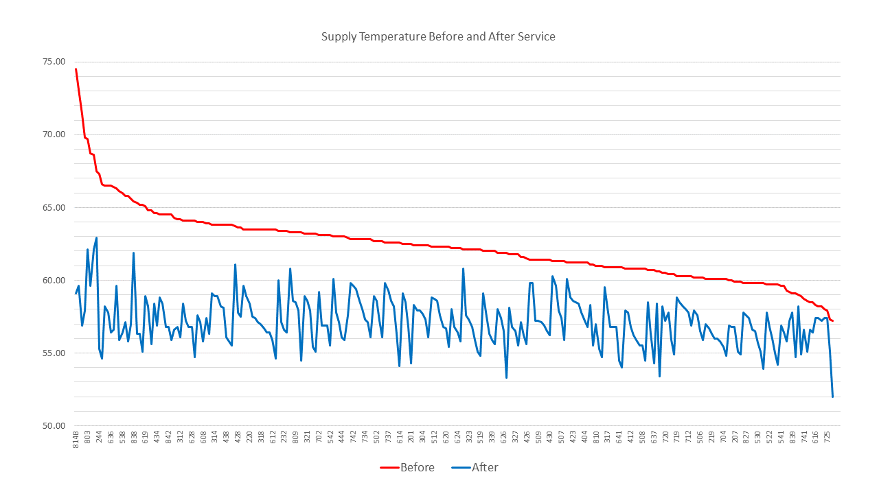
Supply Temperature Before and After Service
Summary: Supply temperature dropped by an average 5.2℉ from 62.3℉ to 57.1℉.
The graph below shows supply temperature sorted from high to low before coil rejuvenation and control valve replacement.
The red line shows that before the coils were rejuvenated the supply temperature ranged from 74℉ to 57℉. The average supply temperature was 62.3℉. The supply temperature was above 60℉ on 86% of the units.
The blue line shows that after service the supply temperature for 96% of the units is below 60℉. The average supply temperature after service is 57.1℉.
FPM Airflow Before and After Service
Summary: Airflow increased from an average of 670 FPM to an average of 910 FPM.
The graph below shows high fan airflow from the bedroom supply vent measured in FPM sorted from low to high before the coil rejuvenation.
The red line shows that before service the high fan airflow ranged from 208 FPM to 1024 FPM. Average airflow was 670 FPM.
The blue line shows that after service the high fan airflow ranged from 553 FPM to 1185 FPM.
Overall the coil rejuvenation increased the airflow by an average 27% from 670 FPM before service to 910 FPM after service. In all units airflow was unrestricted.

Sound Decibels Before and After Service
Summary: Sound decibels reduced from an average of 60.79dB to 56.65dB.
The graph below shows sound decibels measured from the bedroom supply vent sorted from high to low before service.
The red line shows that before service sound decibels ranged from 76.1dB to 53.6dB, averaging 60.79dB.
The blue line shows that after service sound decibels ranged from 65.2dB to 52.1dB.
Overall the service reduced sound decibels by an average 7% from 60.79dB before service to 56.65dB after service. After service 97% of the units sound measure below 60dB or less. 60dB is the acceptable measurement for new units.

RESULTS SUMMARY
FACILITY BENEFITS
The project resulted in the fan coil units performing more efficiently. The benefits to the facility are the following: